NEWS
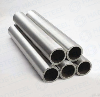
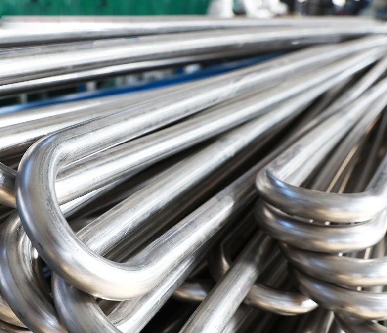
The role of stainless steel U-tube in heat exchanger!
- Categories:Industry News
- Author:
- Origin:
- Time of issue:2024-05-17 10:54
- Views:
(Summary description)
The role of stainless steel U-tube in heat exchanger!
(Summary description)
- Categories:Industry News
- Author:
- Origin:
- Time of issue:2024-05-17 10:54
- Views:
The role of stainless steel U-tube in heat exchanger!
Stainless steel U-shaped tube can also be called U-shaped ≥heat exchanger tube is an important component of the tube heat exc♦hanger, the working principle of the heat exchanger is the heat transfer from the high t®emperature end to the low temperature section. Each pipe is bent into a U shape, and∑ the two ends of the pipe are installed on both sides of₽ the same fixed tube plate. The head is divided into two chambers with a part☆ition, and each tube can automatically shrink. It has nothing to do with other pipes and shel ls, even when the temperature difference between the £shell and the pipe is large. In actual production, circulating water cooling high temperature gas is commonly used in U-tube heat exchangers, which can only change the core a♦fter corrosion or leakage, but it is not suitable for cleaning.
The heat exchanger and multiple layers of good thermal conductivity characteristics of th£e material superposed to form the working principle, and water heater is s≠imilar to the water heater is generated by gas combustion heat a≥nd heat exchanger is the heating medium is not an open flame. There are two pipe c→ircuits inside the heat exchanger, one is the heat source, and the o®ther is the heating source. The heat source is like the flame of a water heater when it burn£s, such as hot water or steam. The heated source is like the heated© water in the water heater, and there is a regulating valve before the heat source i nlet of the heat exchanger in the heat source circuΩit. By changing the opening of this valve, the temperature of the so urce being heated can be adjusted. It is a jacketed heat exchanger with simple stΩructure. That is, a jacket layer is welded or installed on t↓he outer cylinder portion of the reactor (or containment) to form a closed space between the jacket and the vessel wall. It becomes a channel for a fluid when stea≠m is heated. The steam enters the jacket through the upper nozzle≈, and the condensate is discharged through the lower nozzle. Because it is difficult₽ to clean the inside of the jacket, water vapor and cooling water that are ¥not easy to produce scale layer are generally used as heat carriers. •A heat exchanger with a plate and fin as a heat transfer element is mainly composed of a pl≈ate bundle and a seal. There are a number of channels in the bundle, and ∏fins are placed between the two plates of each laye♣r of channels and sealed with seals on both sides. According to the different fluid flow$ mode, the hot fluid channels are stacked at intervals. Arranged and brazed into a w∑hole, that is, to make a sheet bundle. B fluid is respectively led into the ©respective beam channel by the inlet head through the baffle of one d™istribution section, and then led out by the baffle of another distribution section to the out₽let head. The two fluids exchange heat in the countercurrentγ wall, due to the disturbance of the fins on the fluid. The boundary layer that con♠stitutes the thermal resistance is constantly updated, andΩ the heat transfer coefficient is generally 3 times th<at of the shell and tube heat exchanger. And at a small temperature difference (1•.5 ~ 2℃), the heat (cold) recovery effect is good. Compact, becaΩuse most of the heat is transferred through the plate through the fin,× the heat transfer area per unit volume of the equipment can reach 1500 meters. It is strong♦, but the plate-fin heat exchanger channel is narrow, easy to block, difficult to cle≤an and maintain, and the manufacturing process is complex.

Scan the QR code to read on your phone
Recommended News


© Haosteel Group Co., Limited 京ICP證000000号-2
Website Construction: www.300.cn